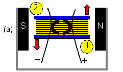
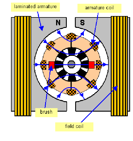
A simple dc motor consists of coils of wire wound on an iron armature in a magnetic field as shown below. A set of brushes and a commutator allow the current always to flow in the same sense.


A rapidly varying electric current (AC or DC) is unsuitable, however, for most electrical appliances and uses. Many such applications require a steady almost constant emf. If your lights were supplied by a 50 Hz AC power supply for example, you would see them flickering and the current rose and fell. The emf/current can be smoothed by using three or more coils in a generator, offset from each other by 120°. Each coil produces single phase AC which is transmitted over power lines separately from the other two phases. When the current from all three phases is superimposed, a smother output is produced (either AC or DC, depending on whether a rectifier has been used). This three-phase supply is commonly used in industrial and domestic power supply and uses generators with three sets of stator coils as shown below.