

The![]() - type flip flop is the most common flip-flop in use today. It is better known as delay flip-flop (as its output
- type flip flop is the most common flip-flop in use today. It is better known as delay flip-flop (as its output![]() looks like a delay of input
looks like a delay of input![]() ) or data latch.
) or data latch.
The![]() output takes on the state of the
output takes on the state of the![]() input at the moment of a positive edge at the clock pin (or negative edge if the clock input is active low). It is called the
input at the moment of a positive edge at the clock pin (or negative edge if the clock input is active low). It is called the![]() - flip flop for this reason, since the output takes the value of the
- flip flop for this reason, since the output takes the value of the![]() input and delays it by one clock cycle. The
input and delays it by one clock cycle. The![]() - flip flop can be interpreted as a primitive memory cell, zero-order hold, or delay line. Whenever the clock pulses, the value of
- flip flop can be interpreted as a primitive memory cell, zero-order hold, or delay line. Whenever the clock pulses, the value of![]() is
is![]() and
and![]() otherwise. The truth table is shown below.
otherwise. The truth table is shown below.
|
Clock |
|
|
|
|
Rising Edge |
0 |
0 |
|
|
Rising Edge |
1 |
1 |
|
|
Non – Rising |
|
|
('![]() ' indicates the signal is irrelevant)
' indicates the signal is irrelevant)
Most![]() - type flip flops in integrated circuits have the capability to be forced to the set or reset state (which ignores the
- type flip flops in integrated circuits have the capability to be forced to the set or reset state (which ignores the![]() and clock inputs) like an SR flip-flop. Usually, the illegal
and clock inputs) like an SR flip-flop. Usually, the illegal![]() condition is resolved in
condition is resolved in![]() - type flip flops. By setting
- type flip flops. By setting![]() the flip flop can be used as described above.
the flip flop can be used as described above.
|
Inputs |
Outputs |
||||
|
S |
R |
D |
> |
Q |
Q' |
|
0 |
1 |
X |
X |
0 |
1 |
|
1 |
0 |
X |
X |
1 |
0 |
|
1 |
1 |
X |
X |
1 |
1 |
4-bit serial-in, serial-out (SISO) shift register
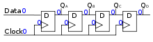
These flip flops are very useful, as they form the basis for shift registers, which are an essential part of many electronic devices. The advantage of the![]() - flip flop over the
- flip flop over the![]() - type "transparent latch" is that the signal on the
- type "transparent latch" is that the signal on the![]() input pin is captured the moment the flip flop is clocked, and subsequent changes on the
input pin is captured the moment the flip flop is clocked, and subsequent changes on the![]() input will be ignored until the next clock event. An exception is that some flip flops have a "reset" signal input, which will reset
input will be ignored until the next clock event. An exception is that some flip flops have a "reset" signal input, which will reset![]() to zero, and may be either asynchronous or synchronous with the clock.
to zero, and may be either asynchronous or synchronous with the clock.
The above circuit shifts the contents of the register to the right, one bit position on each active transition of the clock. The input![]() is shifted into the leftmost bit position.
is shifted into the leftmost bit position.