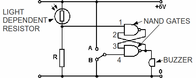
Simple circuits made of up the different types of logic gates – NOT, OR, AND NOR, NAND, XOR, XNOR – can be used to perform simple and useful tasks. Because the circuits are simple and the logic gates are reliable and mass produced, the circuits are reliable.
One such – a light activated burglar alarm – is shown below.

NAND GATES require both inputs to be 1 before a zero output is produced. Since the buzzer will sound when there is a voltage across it, this requires the upper input to the buzzer to be at a positive voltage. When there is no light, the resistance of the LDR is infinite so the input 1 is zero. The output 3 is then 1, so if the switch is set to A the bottom input to the bottom NAND GATE is 1 and the output from the bottom NAND gate is 0. The buzzer will stay silent.
When light falls on the LDR, the voltage across it will fall so input 1 can rise to 1. This trips the switch to B, so that input 4 is now 0, input 3 is 1 and output 2 is 1. The buzzer sounds and keeps sounding until the switch is reset to out. The various outputs and inputs are shown in the table below.
|
Light On/Off |
Switch A or B |
Input 1 |
Input 2 |
Input 3 |
Input 4 |
Buzzer |
|
On |
A |
1 |
0 |
1 |
1 |
Off |
|
On |
A |
1 |
1 |
0 |
1 |
On |
|
Off |
B |
0 |
1 |
1 |
0 |
On |
|
On |
B |
1 |
1 |
0 |
0 |
On |
|
Off |
A |
0 |
0 |
1 |
1 |
Off |
