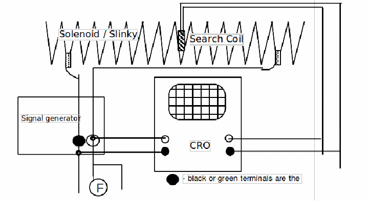
Apparatus:
Slinky coil to be the long solenoid, two crocodile clips, search coil, dual beam oscilloscope, signal generator, frequency meter, wires, 3 x clamp stands etc..
Diagram:

Procedure:
1. Connect at least half the length of the slinky to the signal generator.
Support the coil along the bench using two of the clamp stands so that the distance between the crocodile connections is at least one metre with at least twenty turns of the coil between the clips. Check that adjacent coils are not touching each other. Use the low impedance or 'LS' terminals. Set this generator to 1.0 kHz SINEWAVE.
2. Connect one trace of the CRO to the signal generator and the other trace to the search coil.
3. Clamp the search coil into the middle of the slinky so that the plane of the coil is perpendicular to the axis of the slinky coil.
4. The varying current in the slinky coil causes varying magnetic field which in turn induces a varying emf in the search coil. This emf is directly proportional to the magnetic flux density if the search coil is kept at the same orientation to the field. The current through the slinky coil will also be proportional to the voltage applied to the coil. Therefore the peak to peak measurement of the oscilloscope trace will be proportional to all of these.
5. By changing the distance between the crocodile clips but not the number of turns of the slinky coil, show that the magnetic flux density inside the coil is proportional to, n the number of turns of the slinky per unit length of the slinky. You should draw a suitable graph.
6. Why is it important not to vary the number of turns in stage 5?
