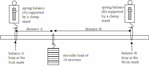
Apparatus:
Metre ruler; 2 x 10N spring balances; set of 100g masses; 2 x clamp-stands with clamps and bosses; three cotton loops
Diagram:

Procedure:
1. Set up the apparatus as shown above. Notice where the spring balances (A and B) are used to support the metre ruler. Place the load of 10 newtons so that distance A = 30cm and distance B = 60cm.
Adjust the positions of the clamps so that the metre ruler appears to be HORIZONTAL.
2. Note down the readings on each of the spring balances in newtons. Add the two readings together.
3. Repeat the above for about seven other different positions of the load. Remember to keep the metre ruler HORIZONTAL.
4. Tabulate your measurements and calculations.
5. Plot a graph of Spring balance reading A (in N) against Distance A (in cm).
Use the same graph above to add, using a different colour, a line for Spring balance B against Distance A.
6. Explain or calculate:
(a) Why the load of 10N is less than the sum of the spring balance readings.
(b) The weight of the ruler.
(c) The variation in the spring balance readings with the position of the load.
7. The diagram below shows a bus about to pass across a bridge that is supported by columns A and B.
Use your measurements and graph to help you answer the questions below this diagram.
![]()
![]()
When the bus is between the columns:
(a) Describe how the force experienced by column A varies as the bus travels across the bridge.
(b) Describe how the force experienced by column B varies as the bus travels across the bridge.
(c) When does column A experience (i) the maximum; (ii) the minimum force?
(d) When does column B experience (i) the maximum; (ii) the minimum force?
(e) When do the two columns experience the same force?
When the bus passes column B:
(f) How does the force at column A change?
(g) What could happen at column A once the bus has passed column B?
