Apparatus:
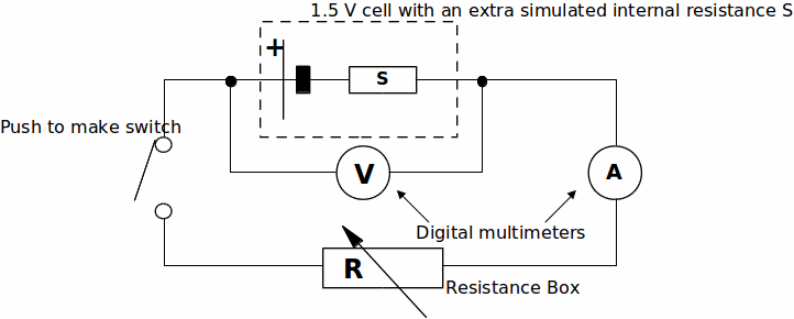
1.5V cell, Mounted and taped unknown resistor labelled 'S', push to make switch, 0 to 1000 OHM resistance box, two digital multimeters, wires.
Diagram:

The internal resistance,![]() of a
of a![]() cell is typically about
cell is typically about![]()
To prevent damage to the cell, you are going to pretend that the resistor labelled 'S' is also inside the cell.
The dashed lines in the above diagram will represent the boundary of the 'modified' cell.
The resistor box will act as the external resistance,![]() of this circuit.
of this circuit.
Procedure:
1. Adjust the resistor box so that it has a resistance of![]()
2. Set up the circuit as above.
3. Measure the current through the cell (I) and the potential difference across the cell (V)
for values of![]() and
and![]() IN THIS ORDER
IN THIS ORDER
DO NOT PRESS DOWN THE SWITCH LONGER THAN NECESSARY
4. Tabulate the values of![]() &
&![]() in a suitable table.
in a suitable table.
5. Draw a graph of![]() / volts (
/ volts (![]() - axis) against
- axis) against![]() / A (
/ A (![]() - axis). It should be a straight line of negative gradient.
- axis). It should be a straight line of negative gradient.
(NOTE: Plot current in amperes!)
6. Measure the![]() intercept. This should equal the EMF of the cell.
intercept. This should equal the EMF of the cell.
7. Measure the gradient of your graph. This will equal the negative of the combined resistance of resistor 'S' and the actual internal resistance r of the cell.
8.![]() equals the power being transferred by the cell to the external resistance
equals the power being transferred by the cell to the external resistance![]()
Draw a graph of![]() / watts (y - axis) against
/ watts (y - axis) against![]() /
/![]() (
(![]() - axis). It should be a curve with a maximum.
- axis). It should be a curve with a maximum.
Approximately what value of![]() yields the maximum power transfer?
yields the maximum power transfer?
How does this compare with the 'modified' internal resistance?
THEORY:
For a complete circuit![]()
where![]()
The voltmeter reading,![]() is equal to the external potential difference,
is equal to the external potential difference,![]()
Therefore![]() and so
and so![]() rearranged is
rearranged is![]()
The equation is now in the form![]() is equivalent to
is equivalent to![]() to
to![]() to
to![]() the gradient and
the gradient and![]() to
to![]() the y-axis intercept.
the y-axis intercept.
Hence the gradient of the![]() against
against![]() graph is equal to
graph is equal to![]() and the intercept with the y-axis to
and the intercept with the y-axis to![]()
