Apparatus:
Lab PSU set at 8V, two digital multimeters (one set at![]() dc the other at
dc the other at![]() dc), reed switch box, parallel plate aluminium capacitor with insulating sheet, 0.01µF capacitor, small plastic squares (in a box usually), micrometer, frequency meter set on 2kHz, signal generator set initially at 50Hz sinusoidal.
dc), reed switch box, parallel plate aluminium capacitor with insulating sheet, 0.01µF capacitor, small plastic squares (in a box usually), micrometer, frequency meter set on 2kHz, signal generator set initially at 50Hz sinusoidal.
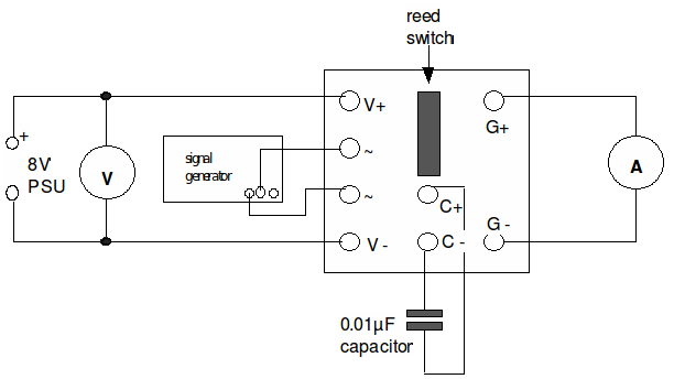
Diagram:

Note: In addition the frequency meter should be connected to the output of the frequency generator.
Theory:
The signal generator controls a reed switch. This is a switch that at first connects the supply voltage (approx. 8V) to the capacitor. The capacitor charges and stores a charge![]() given by the equation:
given by the equation:
![]()
A few moments later the switch then moves in such a way as to connect the capacitor to the ammeter. The capacitor discharges over a time![]() the current
the current![]() flowing being given by:
flowing being given by:
![]()
The above cycle repeats itself at a frequency equal to twice that of the signal generator’s frequency ,![]() Therefore in a time
Therefore in a time![]() seconds a charge
seconds a charge![]() is transferred via the capacitor from the power supply to the ammeter.
is transferred via the capacitor from the power supply to the ammeter.
![]()
and so:
![]()
Procedure:
(a) Measurement of capacitance
1. Set up the apparatus as shown in the above diagram. Set the power supply to![]() dc and the signal generator to 50Hz sinusoidal. Turn up the output of the signal generator until you hear the reed switch buzzing steadily. At this point the voltmeter should be reading about
dc and the signal generator to 50Hz sinusoidal. Turn up the output of the signal generator until you hear the reed switch buzzing steadily. At this point the voltmeter should be reading about![]() and the ammeter about
and the ammeter about![]()
2. Obtain current readings for a range of frequencies between 50Hz and 500Hz. The current should rise over this intervals and you may need to increase the output from the signal generator in order to keep the reed switch operating.
3. Draw a graph of current (I/A) against frequency (f/Hz).
4. Use the gradient of this graph to calculate the capacitance of the capacitor.
(b) Measurement of permittivity
5. Set the signal generator at 200Hz and replace the 0.01µF capacitor with the aluminium
parallel-plate capacitor as shown in the diagram below:

6. Record the current & voltage for this case and also measure the area![]() of overlap of the plates and the thickness d, of the insulating sheet.
of overlap of the plates and the thickness d, of the insulating sheet.
7. Repeat stages 4 & 5 but this time with an air gap between the plates. Use the small plastic squares to separate the plates.
8. Use the current, voltage and frequency values to calculate the capacitances in the above two cases using![]()
9. The capacitance of a parallel plate capacitor is also given by![]() where
where![]() is the permittivity (in
is the permittivity (in![]() ) of the insulation. Calculate the permittivity in both of the above cases.
) of the insulation. Calculate the permittivity in both of the above cases.
10. The value with the air gap should be approximately the permittivity of free space o.
Use this value to calculate the relative permittivity![]() of the plastic insulation given that
of the plastic insulation given that![]() where
where![]() is the permittivity of the insulating sheet.
is the permittivity of the insulating sheet.
