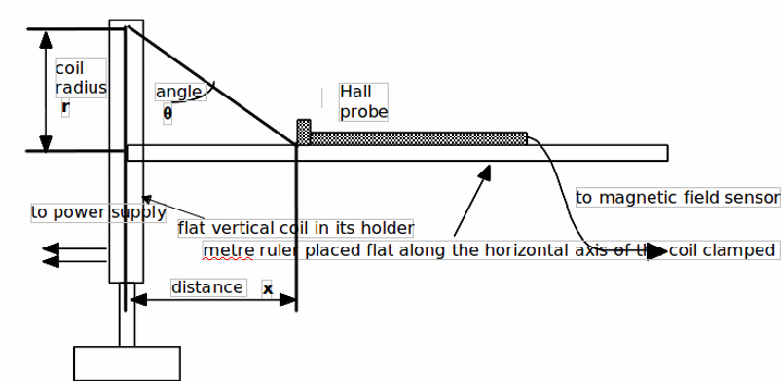
Apparatus:
Hall probe and magnetic field sensormeter, bar magnet, single flat coil (helmholtz), coil holder, metre ruler, clamp stand, lab power supply set on 12V DC, rheostat, multimeter on 10A scale, wires
Diagram:

Procedure :
1. Switch on the magnetic field sensormeter and select the ±10mT scale. The probe attached to this meter measures magnetic fields using the quantity MAGNETIC FLUX DENSITY, symbol B in the unit TESLA (T) (1000mT = 1T).
2. Move the end of the probe around the bar magnet and notice how the reading varies in magnitude and sign. Notice in particular how the orientation of the probe affects the reading obtained. (There is no need to record any measurements at this stage.)
3. Refer to the diagram shown below. Clamp your metre ruler horizontally so that it lies along the horizontal axis of the flat coil. The zero of the ruler should be positioned at the mid point of the coil. Connect the coil to the lab power supply set at 12V DC via an ammeter and rheostat. Adjust the rheostat so that about 1.5A of current flows through the coil. Maintain this current level throughout the rest of the experiment.
4. ENSURE THAT THE BAR MAGNET IS WELL OUT OF THE WAY. Place the end of the Hall probe at the zero of the ruler, distance![]() The probe should give a reading of about + 5 to + 6 mT. If it gives a negative reading, reverse the direction of current through the coil.
The probe should give a reading of about + 5 to + 6 mT. If it gives a negative reading, reverse the direction of current through the coil.
5. Turn off the current. Record the magnetic background reading of the sensormeter, Bb, this might be zero.
6. Turn on the current again. Record how the magnetic flux density, B varies over distance x = 0 to 10 cm.(Remember to correct your readings for the background flux density, Bb.)
7. Plot a graph of B against distance x.
8. Theory predicts that the magnetic flux density B varies with angle![]() according to the relationship
according to the relationship
![]() where
where![]()
For two values of distance![]() check how well this equation works.
check how well this equation works.
Note: When calculating![]() take the radius,
take the radius,![]() of the coil to be 6.65 cm.
of the coil to be 6.65 cm.
