

Apparatus:
Lab power supply set at 3V DC, mounted silicon diode, two digital multimeters, 2.5V mounted light bulb, rheostat (variable resistor), wires.
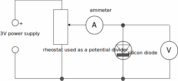
Circuit diagram (diode part):
Procedure:
(a) Silicon diode
1. Wire up the circuit diagram shown. Set the voltmeter to 20V DC and the ammeter to 200mA DC.
Ask your teacher to check this circuit.
2. Record the voltage V required to make the following currents I (in mA) flow through the diode.
Currents of: 1, 2, 5, 10, 20, 30, 40, 50, 100, 150, 200mA. (Note 10mA = 0.01A!), DO NOT ALLOW THE CURRENT TO EXCEED 200 mA.
3. Plot a graph of I/mA against V/volt. THIS GRAPH SHOULD INCLUDE THE 0-0 ORIGIN
(b) Light bulb
4. Replace the diode with a light bulb and measure I as a function of V, increasing I in steps of 10 mA up to 50mA and then in 50mA steps but this time up to the maximum possible.
5. Plot a graph of I/mA against V/volt.
(c) Calculations
6. Calculate the resistance of the diode and light bulb at the following current values: 0mA, 10mA, 50mA, 200mA & the light bulb at maximum current.
(d) Conclusions
7. Describe, in as much detail as possible, what each of your graphs show about the behaviour (in terms of resistance) of the diode and bulb.