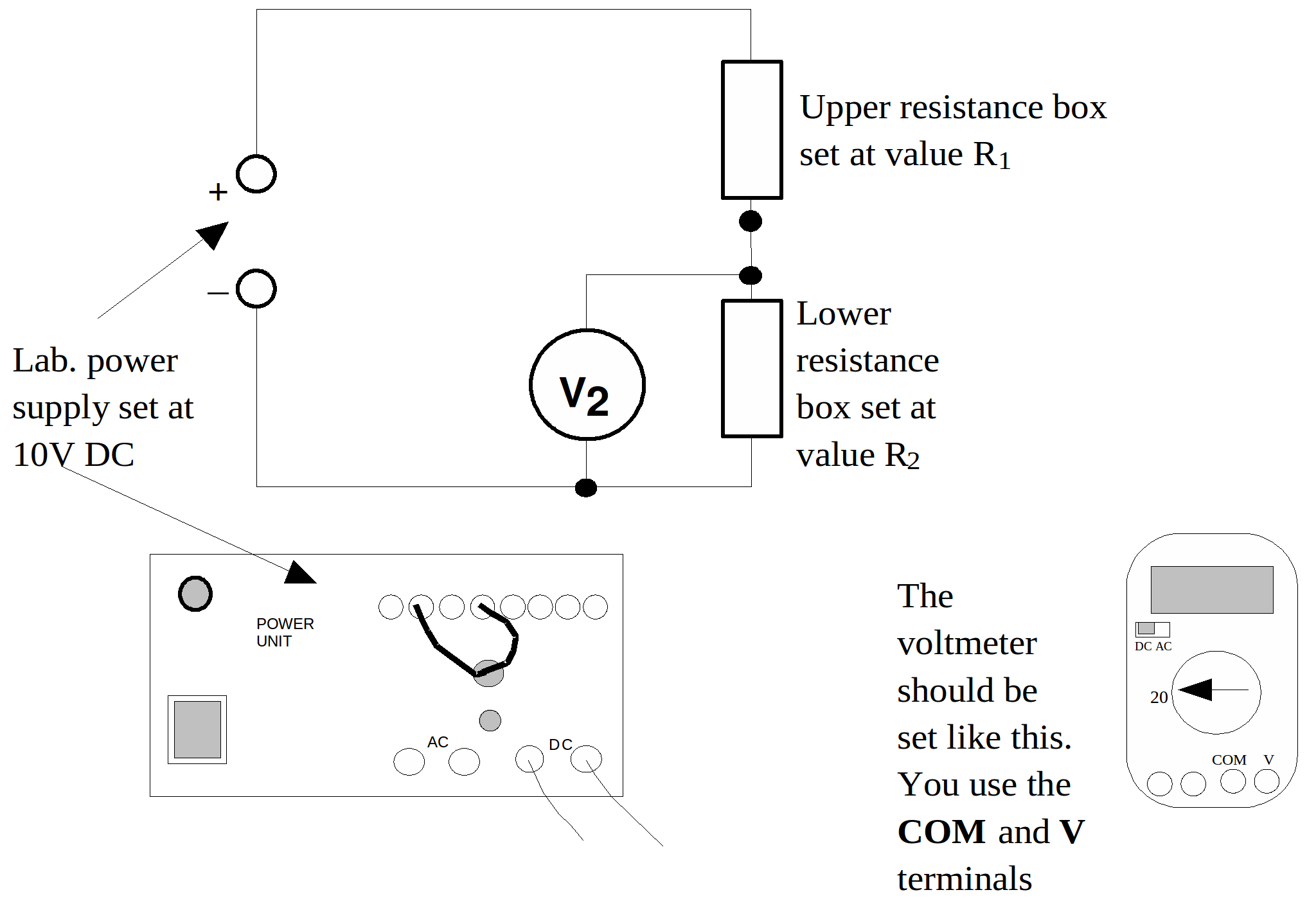
Apparatus:
One digital multimeter set on 20V dc (see diagram below), lab power supply set on 10V dc, two 10kΩ resistance boxes, light dependent resistor, wires.
Diagram:

Procedure:
1. Set up the circuit shown above, with both resistor boxes,![]() and
and![]() set at
set at![]()
2. For a range of values of![]() record the value of
record the value of![]() and calculate,
and calculate,![]()
Note:![]() should remain set at
should remain set at![]() throughout.
throughout.
3. Tabulate your results and then plot a graph of![]() against
against![]()
4. Calculate the gradient of your graph. Your gradient should equal the supply voltage. This may not be![]() !
!
5. Replace![]() with the light dependent resistor.
with the light dependent resistor.
Note and explain (using your previous results) why the voltage levels change as you change the level of light incident on the LDR.
