

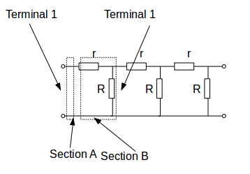
in section A
\[i\]
is the current flowing into and out of terminal 1 and I is the current flowing into and out of terminal 2. Let \[v\]
be the voltage between the input terminals and let \[V\]
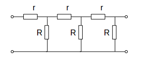
be the voltage difference between the output terminals. A current \[i\]
flowing through a resistance \[r\]
experience a voltage drop \[ir\]
hence \[V=v-ir\]
. The current along the bottom of the diagram is constant - \[I=i\]
.We can represent the input - section A - with the vector
\[\mathbf{w}= \begin{pmatrix}v\\i\end{pmatrix}\]
and the output with the vector \[\mathbf{W}= \begin{pmatrix}V\\I\end{pmatrix}\]
.
We can represent the input and output in matrix form as \[\mathbf{V}= A \mathbf{v}, \: A= \left( \begin{array}{ccc} 1 & -r \\ 0 & 1 \end{array} \right)\]
.Now analyse section B. The input to section B is the output from section A so
\[v=V\]
. A current \[V/R\]
passes through the resistance \[R\]
and the input current at B is less by this amount so \[I=i-V/R\]
. We can represent section B by the matrix system \[\mathbf{V}= B \mathbf{v}, \: B= \left( \begin{array}{ccc} 1 & 0 \\ -1/R+ & 1 \end{array} \right)\]
.The input and output of the circuit representing the wire is
\[\begin{equation} \begin{aligned} \mathbf{OUTPUT} &= (AB)^3 \mathbf{INPUT} \\ &= ( \left( \begin{array}{ccc} 1 & -r \\ 0 & 1 \end{array} \right) \left( \begin{array}{ccc} 1 & 0 \\ -1/R & 1 \end{array} \right) )^3 \\ &= \left( \begin{array}{ccc} 1+r/R & -r \\ -1/R+ & 1 \end{array} \right)^3 \mathbf{INPUT} \end{aligned} \end{equation}\]