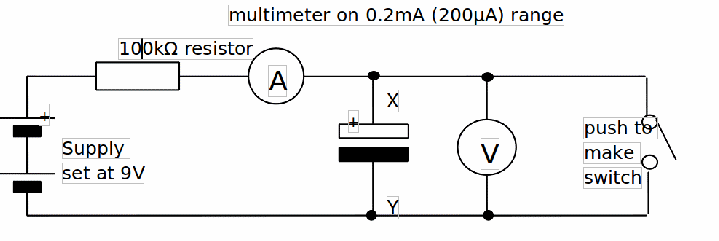
Apparatus:
Two electrolytic capacitors (470µF & 1000µF), 100kΩ resistor, 2 x digital multimeters (one of these should be set on 200µA DC the other on 20V DC), Push-to-make switch, Power supply set on 9V, Stop watch and wires.
Diagram:

Procedure:
1. Set up the circuit above using the 1000µF capacitor and the 100kΩ resistor. Be careful to connect the capacitor the right way around.
2. Once you switch on, the ammeter should register a current that starts to fall from an initial value of about 100µA (0.100mA) to nearly zero over a period a few minutes. If you close the switch, momentarily, this current returns to its initial value of about 100µA before decaying again. The voltmeter will read initially zero and then rise up to about 10V in the same time. Both current and voltage changes are exponential.
3. Take current readings over a five minute period (e.g. every 30 seconds) in order to be able to draw a graph of current (in micro-amperes) against time (in seconds).
At the five minute point note the voltage, V of the capacitor.
4. Repeat with:
(a) the 470µF capacitor and
(b) the 1000µF capacitor connected in series with the 470µF capacitor.
Note: With the combination, the voltmeter should be connected to read the total voltage of the capacitors.
5. Tabulate all your results.
6. ON THE SAME AXES plot graphs of current (in micro-amperes) against time (in seconds)
for the three above current variations.
7. In each case estimate (nearest cm2 will do) the area between each curve and the time axis.
This area will equal the charge Q (in micro-coulombs) transferred to the capacitor(s) after five minutes.
(Example of area calculation: If your axes scales are 1cm = 10µA & 1cm = 30s then each square cm on your graph will represent a charge of 10µA x 30s = 300µC)
8. Use this charge value and the capacitor voltage to calculate the capacitance of the capacitor or capacitor combination using the formula![]()
9. Compare your calculated values with the marked values and with those expected by using the formulae for capacitors in series and parallel (see below).
For two capacitors (C1 & C2), connected in series, the total effective capacitance,![]() is given by
is given by
![]()
